Thursday, June 26, 2014

Testing the printer

Last weekend I was able to get through almost all the steps to my first print.  Here were some of the stumbling blocks:


  • Remember the knob for the display?  In my last post I said it looked like I needed to clear out some support material.  Well, it looks like I was just supposed to shove it on.  When I cleared out all the support material, there was no way to fasten the knob on.  No big deal, though.  I can just print a new one when I get the printer working.
  • I was able to get the X, Y, and Z axes moving just fine under manual electric control.  The Z axis was a bit squeaky at first, but I used some teflon lubricant and now the noise is gone.
  • In the first (manual, non-electric) leveling step, it's kind of hard to visually estimate the distance between the hot end tip and the build plate.  Then when I got to the fine adjustment stage I had difficulty getting the two hot ends exactly level.
  • The final step before doing the first test print was to heat up the hot ends and extrude some filament under manual control.  The instructions talk about adjusting the tensioning bolt to get it tight, but not too tight.  Too tight can cause a clogged extruder.  I fiddled with this for a while, but couldn't get the extruder wheel to grab the filament.  
At this point I was thinking that between the difficulty leveling the hot ends vs. each other and the difficulty getting the filament to grab, I should take a second look at the extruder assembly.  When putting it together, we had trouble with a couple of vertical bolts that didn't seem to be grabbing with the nuts inside the assembly.  So I removed the outer fan and took a look.  Sure enough, one of the nuts had grabbed, but the other had just been pushed aside in its slot.

As a reminder, this is how those nuts were inserted into the assembly...


Here's what it looks like from the side, with the nuts flat.  They are supposed to be pinched enough in their slots so that they won't turn, and you can thread the bolt through to firmly fasten the extruder assembly onto the X-axis shuttle.


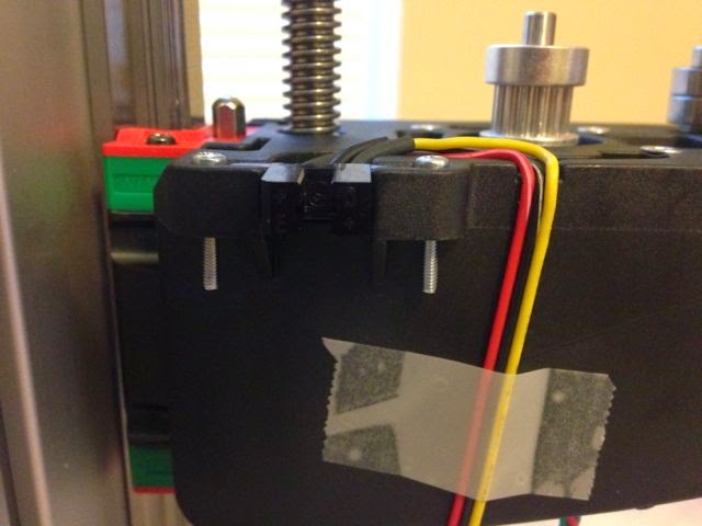
Here's what I found when I looked at that from the bottom.  The one on the right threaded just fine, but the one on the left wouldn't.  I sent a copy of this photo to the manufacturer, and they agreed that the plastic part on the left was defective.  The cutout for the nut should be a symmetric half-circle.  Probably the missing material there was why the nut wouldn't stay in place.  They are sending me a replacement part, but it hasn't arrived yet.  I did get one other suggestion from the discussion boards; use a thick nut instead of a thin one.  I was able to find thick M4 nuts at Home Depot without any difficulty, and will substitute them when the new part comes.


Last night I also was able to resolve the extrusion issue.  I just had to tighten the tension bolt a little more than I had initially been comfortable with.  

When the replacement part comes, I should be able to get the two hot ends level and be good to go for the test print.  Just a little longer!

Saturday, June 21, 2014

Finishing the build

My friend Bill Hegarty from work came over again today, and together we finished building the printer with around 5 hours of work.  It was relatively straightforward work, which Bill gets most of the credit for.  Really a one-person job for the most part.  We did encounter a few minor problems, though:

  • When attaching the kapton sticker to the build plate, a speck of metal (FOD!) somehow got onto the plate and created a dimple.  We peeled the sticker back a bit, removed the speck, and proceeded onward.  I think getting a very flat surface is very important on that step.
  • We had not labeled the fan wire ends (wasn't called out in the instructions that we were supposed to), so when we got to the point of connecting them up, we weren't sure which was which.  The solution was to grab a 3V CR2032 battery and test to see which wires made which fans move when connected.  This worked well, and we were quickly able to establish which fan was which.
  • There was a step missing for inserting flat nuts into their slots in the power supply case, so when we went to close the power supply up, there was nothing for the bolts to screw into.  This was easily corrected.
  • The instructions say that the board is sensitive to ESD (electrostatic discharge), but I didn't have a good grounding station.  Our solution was to plug in the power supply (establishing a ground) and then clip my grounding strap to one of the power supply screws.  I hope this worked.   Of course we were careful to make sure the power switch was off!
  • The 3D-printed knob for the display didn't have an opening for insertion on either side!  Looks like there is support material that needs to be cleaned out.


See below for a picture of the wired-up board.  Again, Bill gets the credit for doing most of this.  My count was 57 wires to be attached.


Front and back pictures of the assembled printer:


Me and Bill posing with the completed printer:


When the job was done, there was still a fair amount of leftover material


In particular, there was a thermistor that was unused.  I think this is a spare in case one of the hot-end thermistors dies.  A few of the pieces are clearly intended for the filament spool and cleaning accessories to be added later (I have to print the main parts).

Tonight I finished annotating my PDF copy of the assembly manual and uploaded it to the support board.  Also ordered a couple of kilos of PLA filament from Amazon.  Tomorrow I will start going through the User's Guide and see if I can do my first print!


Thursday, June 19, 2014

More iterations on the toolbox


So while I've been working on the 3D printer kit at home, I've continued to play with the 3D printers at work.  Here's my design for a toolbox with a lid that actually opens and closes.  It uses a dimpled hinge concept.  The trick is that there has to be enough flexibility in the end pieces to insert the lid, but without breaking it.


The first try didn't work at all, as I couldn't get the hinge in without breaking the hinge side pieces.  So I modified the design a bit, putting a slot into one of the side pieces as shown below:


This worked better, but with the 4 cm base box length I still ended up bending the end piece and breaking it off.  So I scaled up by 1.5x.  Rationally, one knows that 2x length yields 8x volume, but  I think the picture below really dramatically illustrates what a big difference that makes.  The 1.5x box is huge compared to the original.  But you can see that the right-hand hinge edge still ends up getting bent by the insertion process.


Thickening up the hinge end pieces a bit seems to do the trick, though, and the final version snapsin and works just great.


This was printed in ABS on a Makerbot 2x we have at work.  It has a dual extruder and heated bed, just like my Felix 3.0.  It will be interesting to compare print quality.  A problem did show up with the printing process; one corner sags substantially.


The guy who is responsible for the printer thinks it's sagging because the Kapton tape on the print bed is getting worn, affecting the adhesion of the initial layer.  People on the Felix support boards have talked about similar issues, including deformation of the build plate due to printing of large objects.  The boards didn't explain why the deformation occurs, but I'm thinking it is happening because ABS shrinks a bit while it cools; since it shrinks while still stuck to the build plate it can exert a bowing force.  Even a little deformation can ruin the leveling of the plate and affect the print quality.  One possible fix that is talked about on the boards is using a (cheap) glass plate clipped to the build plate instead of a Kapton covering.

As a final note, here's a photo of the prototype we did up for our Matlab competition's trophy.  This was printed from Shapeways.com using their color sandstone option.  The membrane surface is the Mathworks logo, and was created in Matlab and exported directly to a 3D-printable file.  The final version will be bigger, with some writing in the flat square part.  Holding this thing in your hand really brings home the amazing potential of this technology.


Fixing the sensor

As you will recall from the last post, I had broken a couple of pins on one of the three opto-interrupter limit sensors that came with the kit.  I ordered a replacement sensor from Mouser.com, which arrived in a few days.  I should have really ordered several, as the shipping cost was substantially more than the cost of the individual sensor.

I purchased some soldering equipment from Frys and enlisted the help of a couple of my friends from work.  No shortage of people who know about soldering here in Silicon Valley.  One coworker had already helped me pull out the pin casing of the damaged sensor, exposing the two pins that had been broken off.  Another provided some heat shrink and resoldered the damaged sensor, keeping the new one as a spare.  We couldn't quite finish the job, as I had to run to pick up my daughter from school.  All I had to do was borrow my neighbor's heat gun (basically a high-powered blow dryer) and shrink the tubing to cover up the exposed solder joint.  Didn't think I needed any instructions for that.  After all, how hard could it be?


Hmm, guess I held the gun a little too close. :-)  Good thing I had a spare.  So the next day I enlisted my neighbor's help on the remaining sensor, and he did an expert job with the soldering.  The picture below is a little deceptive.  The two diagonally opposed corner pins were brought together and soldered to the black wire.  The yellow wire is actually going over one of those two pins, but it's kind of hard to see.  Still not done, though, as the heat shrink I had gotten wouldn't shrink enough for a tight fit onto the wire.


Another day, another trip to Frys for more heat shrink, and a little more help from my neighbor and we finally had the third sensor mounted.  This weekend I should hopefully be able to to finish the build.


Saturday, June 14, 2014

Build issues

As mentioned at the end of the previous post, we did run into some issues that will have to be resolved.  First, we had some problems with the nuts in the extruder assembly.  In the photo below, the six flanges slot into the X axis carriage.  For the single-extruder version, you'd just have the left and right end pieces, with the extruder motor and hot end between them. For the dual-extruder version, the center piece is added to mount the extruders side by side.  The issue is with the two nuts at the bottom between the two end pieces and the center piece.  Those nuts are just sitting there in hexagonal slots formed by the pieces on either side, and are free to move up and down.  The fit isn't super-tight, so a little jostling while mounting the extruder assembly to the carriage can leave them sitting at an angle.


The bolts that fit in these nuts are used to tighten the extruder assembly on the carriage.  But after the two have been connected, it's impossible to see the nuts.  From the feel of things, it seems like the bolts thread into the nuts OK.  When it comes to tightening them, though, it feels like the nuts are turning in the slot.  Because of the lack of visibility, it's impossible to tell exactly what's going on.  One solution might be to super-glue the nuts in place, but that might bring its own issues.  For now, we're just hoping that it's tight enough. 

The next problem came when attaching the second optical sensor.  Here's what the diagram shows:


Unfortunately, the 9mm screws that came with the kit aren't long enough to bite, so I couldn't clamp the sensor in place.  Since I live in the US, not Europe, I couldn't find 16mm metric screws to use as alternatives.  I was able to find some English units screws at my local electronics supply store that seem to do the trick, though as shown below they do jut out a bit.


The second problem here was with the wire routing.  As you can see in the diagram below, the wires from the sensor are supposed to lie flat in the groove cut out of the plastic part.  I had a really hard time doing this, and ended up breaking the connection between wire and case on one of the sensors.  The picture above shows my final result with my last remaining sensor from the kit.  Still not flush, but at least I didn't break the wire on the second try.  Now I have to wait for a replacement part to arrive before I can do the third sensor.


Below you can see that the middle (black) wire was just soldered onto two diagonally opposed pins that had been bent in to meet in the middle.  Not very robust to bending.


In fact, on the FelixPrinters web site list of replacement parts, they sell sensors with the appropriate bend for the 3rd sensor built in.

Now I'm in waiting mode until I get my replacement sensor in the mail and have a go at soldering it properly myself.


Tuesday, June 10, 2014

Assembling the Printer, Part I


Saturday was spent cleaning the study to the point where the printer assembly could begin.  Ugh.

Assembly started around noon on Sunday.  Here's the contents of the box, unpacked.


The fasteners came in their own box, sorted in the order called out in the bill of materials.  Nice!


I did a check of the contents of this box vs. the bill of materials.  There appeared to be a few extra fasteners, but I think that may be because I ordered the dual extruder option.  We'll see if I have anything left over when the assembly is done.  One of the items in the miscellaneous bag was a pair of fine tweezers, useful for picking up the tiny nuts and washers.

The instructions are fairly clear, if obviously translated from Dutch.  Lots of good diagrams, and divided into discrete tasks with estimates of time to complete.  The web site said I might need a variable speed drill, but there have been no signs of that yet.  There was one odd tool called out that no one I knew could identify.  I found out to day it is a type of adjustable wire stripper.


 First step, build the frame...


Not too hard.  With the help of my friend Bill, I was able to get through the assembly of the X and Z axis drives without too much difficulty.


One issue we did run into was that the orientation of the Z axis cart wasn't super clear from the diagrams.  One end had just a screw over the real, and the other a knob sticking out.  Our best guess was that the knobby end was supposed to go as shown in the pictures below.


Also, on step 22, where you were supposed to fit the Z-axis carrier on top of the aforementioned cart, we had to use a little pressure.  The cart is rectangular, but the opening that fits over it is slightly trapezoidal.  So you had to fit the wider, back part on first and then depend on some compliance to get the front part to fit over.


This is where we got to by around 5PM.  This was up to around step 70, and about 60% through the entire assembly.  X and Z axes complete, Extruders and some sensors mounted.  Lots of wires hanging around.  After assembling the build platform and Y axis drive, a lot of the rest of the steps are just routing the wires.


Just noticed now that their advertising pictures either conveniently leave out all the wires...


...or present the pretty side, with a lot of the wire routing invisible:


We started running into a few hiccups at the end of the day, which I'll go into in my next post.

First Printed Item

Here are some photos of what the toolbox from the previous post looked like when printed on a Makerbot Replicator 2.  The engraved writing came out pretty well, but the embossed writing on the inside of the lid was a bit ratty.  The guy managing the printer says that was largely because he chose to build with supports, and the letters are at a 45 degree angle, so each letter has its own mini supports which were not really easily removable.  Doing the as a separate piece in the next iteration so that the letters would be straight up and down will probably be more successful.  Also printing the whole thing a bit larger would probably help.


When originally printed, there was a lot of support material holding up the lip of the open lid.  It was too thick to just snap off, so I borrowed a friend's Dremel tool to take it off. 


In this photo you can see I got a little too aggressive and sanded off some of the material that was supposed to be there (bottom right).  I also tried some fine sand paper to see if I could smooth out some of the banding from the print; this caused the ugly marks you see below.  According to a site I found, this is one of the differences between using PLA and ABS filament.  The Makerbot uses PLA only.  ABS is supposed to be easier to sand, and can also be finished using acetone.


I've iterated on the design a bit, but been unable to print it at work, as the Makerbot is out of commission due to a failed temperature sensor.  Hopefully it won't be long until the Felix 3.0 is up and running so I can print at home.


Thursday, June 5, 2014

Hmm, the toolbox image didn't come out in the first post.  Let's see if this works:


Got my 3D printer kit today

My first 3D printer kit arrived in the mail today.  I'm assuming it will be the first of many over the course of the next few decades.  I think this is comparable in many ways to the first computer my family bought when my brother and I were about the same age as my kids are now: an Apple II+.  I'm hoping that this will be as memorable an event in my kids' lives as that was in mine.  Maybe this time I can capture some of the magic.

3D printer kit fresh from Holland

So what prompted me to buy a 3D printer?  I've been reading about additive manufacturing in various forums for several years now, but what made me realize that these were in reach of the average consumer was the Makerbot Replicator 2 that appeared in a demo space to one side of the cafeteria at work, with the message that the folks maintaining it would print any files employees cared to bring in, work-related or not.  Here are a couple things Lockheed Martin is doing related to 3D printing: 


I got to talking about 3D printing with the guys at work, and found out that one person I knew had been playing around with it a fair amount, printing his objects using Shapeways.  He recommended using a piece of software called OpenSCAD to design 3D objects for printing.  An hour or two of checking this piece of software out convinced me that the time was right for introducing this new technology to my kids.  

OpenSCAD is essentially a 3D modeling programming language.  The beauty of this is that it provides almost immediate gratification.  With a few lines of code, kids can make a model that they can then print and hold in their hands.  It has a cool factor that I think is missing from modern introductions to computer programming.  When I was a kid, programming in BASIC, doing ANYTHING on a computer was cool.  Getting it to draw a box on the screen was both easy, and neat.  Today it seems like the barriers to entry-level programming are much higher, and the rewards are comparitively low.  Drawing a box on a screen won't impress anyone.  Coding a box, and then printing it, on the other hand....that's neat.

OpenSCAD primitives are things like box, cylinder, and sphere.  Add to those primitives a few functions for manipulation, rotate, translate, and difference, and you open up a world of possibilities. Kids can learn about programming, geometry, and mechanical design all at the same time.

Here's one of my first attempts.  This was under 15 lines of code.  Make a box, subtract out a slightly smaller one, and you have the bottom.  Do the same thing with a slightly more complex polyhedron and you have the lid.  A cylinder makes the hinge (non-movable in this iteration).  Difference out some text for engravings, add it for embossing.  And then print!  I plan on giving out boxes like this at a competition I'm running to develop tools for a MATLAB library I maintain at work.


So I got to thinking, my kid's school should have one of these printers.  To make a long story short, it's hard to figure out what to buy!  So after looking through Make magazine's 2014 Guide to 3D Printing I decided to buy a printer for myself and use that experience to inform a recommendation to the school.  Last Thursday I settled on the Felix Printers Felix 3.0 with the dual extruder option, and here I am a mere week later with my kit!  The kit with all the options cost about $1900; fully assembled would have been another 450 euros.  When assembled, it should look like this:


I'll talk about the reasons for choosing this particular printer in a later post.