
The bolts that fit in these nuts are used to tighten the extruder assembly on the carriage. But after the two have been connected, it's impossible to see the nuts. From the feel of things, it seems like the bolts thread into the nuts OK. When it comes to tightening them, though, it feels like the nuts are turning in the slot. Because of the lack of visibility, it's impossible to tell exactly what's going on. One solution might be to super-glue the nuts in place, but that might bring its own issues. For now, we're just hoping that it's tight enough.
The next problem came when attaching the second optical sensor. Here's what the diagram shows:

Unfortunately, the 9mm screws that came with the kit aren't long enough to bite, so I couldn't clamp the sensor in place. Since I live in the US, not Europe, I couldn't find 16mm metric screws to use as alternatives. I was able to find some English units screws at my local electronics supply store that seem to do the trick, though as shown below they do jut out a bit.
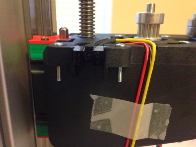
The second problem here was with the wire routing. As you can see in the diagram below, the wires from the sensor are supposed to lie flat in the groove cut out of the plastic part. I had a really hard time doing this, and ended up breaking the connection between wire and case on one of the sensors. The picture above shows my final result with my last remaining sensor from the kit. Still not flush, but at least I didn't break the wire on the second try. Now I have to wait for a replacement part to arrive before I can do the third sensor.

Below you can see that the middle (black) wire was just soldered onto two diagonally opposed pins that had been bent in to meet in the middle. Not very robust to bending.

In fact, on the FelixPrinters web site list of replacement parts, they sell sensors with the appropriate bend for the 3rd sensor built in.
Now I'm in waiting mode until I get my replacement sensor in the mail and have a go at soldering it properly myself.
No comments:
Post a Comment